
SensorNode Documentation
ALL your info is HERE
Here is how to get all your downloadable files, instructions, etc., for your SensorNode!
WARNING: Remember - SensorNode is NOT a consumer product. It is a kit, and all versions assume you have basic knowledge of building electronics. When working with electronics, please take every necessary precaution. If you are soldering, ensure you are properly trained beforehand. Keep your assembly area and yourself properly grounded. Wear eye protection. Changing jumpers, adding/removing components, etc., should only be done with the power OFF and the power supply unplugged. Keep liquids, children, etc., away from the components at all times. Safety FIRST!
Quick Start Guide
If your SensorNode is already assembled, start here.
Just follow the steps below and you'll be up and running in no time.
Parts List / BOM (Bill Of Materials)
If you need to purchase parts for your SensorNode, then the parts lists below will tell you all that you need. You can even download PDFs for printing if you prefer paper.
NOTE: Many of the parts listed below are commodity and therefore can be purchased in many places. You can typically get these parts at JameCo, Adafruit, Amazon, DigiKey, and AliExpress.
SensorNode Board Parts List PDF Version Click HERE
| ID | Name | Designator | Quantity | Manufacturer Part # | Manufacturer | Supplier | Supplier Part # | Source Link | Notes |
|---|---|---|---|---|---|---|---|---|---|
| 1 | 220nF | C1 | 1 | CC1H224ZC1GD3F8A3100 | Dersonic(德尔创) | LCSC | C2761732 | https://www.lcsc.com/product-detail/C2761732.html | |
| 2 | 100nF | C2,C3,C4,C5 | 4 | CC1H104MC1FD3F6C10MF | Dersonic(德尔创) | LCSC | C254085 | https://www.lcsc.com/product-detail/C254085.html | |
| 3 | BM04B-SRSS-TB(LF)(SN) | CN1 | 1 | BM04B-SRSS-TB(LF)(SN) | JST | LCSC | C160390 | https://www.lcsc.com/product-detail/C160390.html | Surface Mount - not req’d |
| 4 | 1N5819_C2474 | D1,D2 | 2 | 1N5819 | MDD(辰达半导体) | LCSC | C2474 | https://www.lcsc.com/product-detail/C2474.html | |
| 5 | DCInputConn | DC1 | 1 | DC005-2.0MM | SOFNG | LCSC | C111567 | https://www.lcsc.com/product-detail/C111567.html | 5.5/2.5 Barrel Jack Center Pos |
| 6 | 20pin-HDR | H1,H2 | 2 | X5511FV-20-C70D30-1000 | XKB Connectivity(中国星坤) | LCSC | C2905423 | https://www.lcsc.com/product-detail/C2905423.html | H1/H2 used to mount Pico W |
| 7 | 2.54-1*4P母 | H3 | 1 | 2.54-1*4P母 | BOOMELE(博穆精密) | LCSC | C2718488 | https://www.lcsc.com/product-detail/C2718488.html | I2C Pin Header |
| 8 | Header-Male-2.54_1x6 | H4 | 1 | 2.54-1x6P直针 | BOOMELE(博穆精密) | LCSC | C37208 | https://www.lcsc.com/product-detail/C37208.html | MUST Short Pins PIN/POUT |
| 9 | JUMPER2 | J1,J2 | 2 | Jumper2 | null | LCSC | C124375 | https://www.lcsc.com/product-detail/C124375.html | 2-pin Jumper Headers |
| 10 | JUMPER3 | J3 | 1 | Jumper3 | null | LCSC | C49257 | https://www.lcsc.com/product-detail/C49257.html | 3-pin Jumper Header |
| 11 | LED-GRN | LED1 | 1 | EDGEELEC | Amazon | https://www.amazon.com/dp/B07PXYZS3P | LED Cable connects here | ||
| 12 | 4.7KΩ | R1,R4 | 2 | MFR-25FRF52-100R | YAGEO(国巨) | LCSC | C120071 | https://www.lcsc.com/product-detail/C120071.html | |
| 13 | 1KΩ | R2 | 1 | MF1/4W-220Ω±1% T | CCO(千志电子) | LCSC | C2894606 | https://www.lcsc.com/product-detail/C2894606.html | |
| 14 | 100Ω | R3 | 1 | MFR-25FRF52-100R | YAGEO(国巨) | LCSC | C2894648 | https://www.lcsc.com/product-detail/C2894648.html | |
| 15 | WJ126V-5.0-2P | S1 | 1 | WJ126V-5.0-2P | KANGNEX(康奈克斯电气) | LCSC | C8404 | https://www.lcsc.com/product-detail/C8404.html | 2-Cond Term Blk |
| 16 | WJ126V-5.0-3P | S2 | 1 | WJ126V-5.0-3P | KANGNEX(康奈克斯电气) | LCSC | C8401 | https://www.lcsc.com/product-detail/C8401.html | 3-Cond Term Blk |
| 17 | SK12D07VG5 | SW1,SW2,SW3 | 3 | SK12D07VG5 | SHOU HAN(首韩) | LCSC | C431548 | https://www.lcsc.com/product-detail/C431548.html | |
| 18 | CD4013BE | U1 | 1 | CD4013BE | TI(德州仪器) | LCSC | C507169 | https://www.lcsc.com/product-detail/C507169.html | |
| 19 | 7805_C2843718 | U2 | 1 | 7805 | PUOLOP(迪浦) | LCSC | C305416 | https://www.lcsc.com/product-detail/C305416.html | 5V Regulator |
| 20 | Pico W | N/A | 1 | SC0919 | RaspberryPi Foundation | DigiKey | 2648-SC0919-ND | https://www.digikey.com/en/products/detail/raspberry-pi/SC0919/18713315 | |
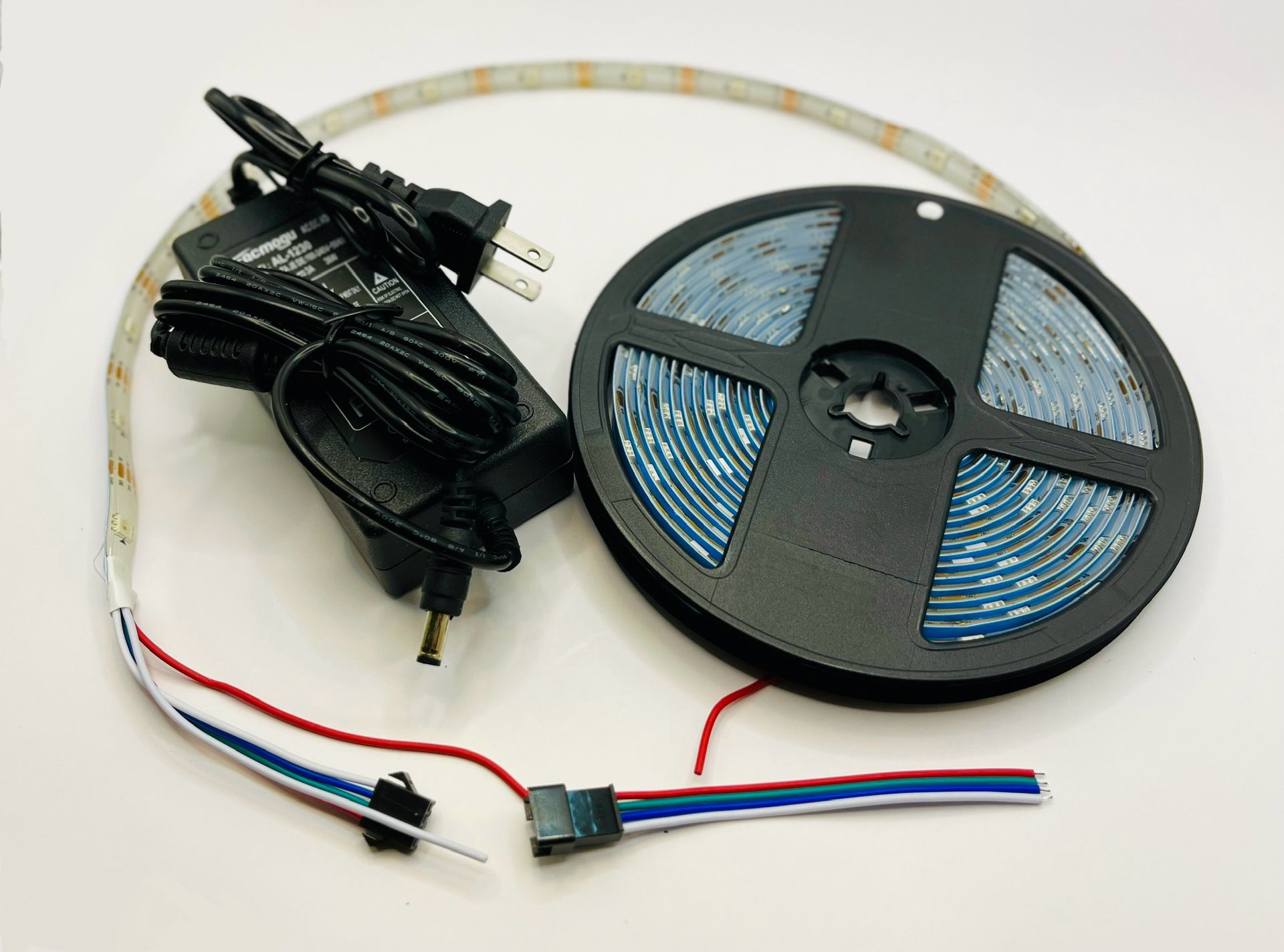
| 21 | Power Supply Option 1 | N/A | 1 | Various | Amazon | Pick One | https://www.amazon.com/dp/B0DYNZ8X55 | 12V or 9V supplies can be used 1A current, 5.5/2.5 adapter Center positive Either will work pick one | |
| Power Supply Option 2 | N/A | 1 | Various | Amazon | Pick One | https://www.amazon.com/dp/B0DYP12V3W | |||
| 22 | Jumper Block | N/A | 4 | Various | Amazon | Click here | https://www.amazon.com/dp/B09WTVZCWY | For J1,J2,J3,H4 |
SensorNode Sensors PDF Version click HERE
These sensors have been personally tested by me to work with SensorNode. Use anything else at your own risk :)
| ID | Name | Manufacturer Part # | Manufacturer | Supplier | Supplier Part # | Source Link | Notes |
|---|---|---|---|---|---|---|---|
| 1 | S2 PIR Motion Sensor | Adafruit | 189 | https://www.adafruit.com/product/189 | |||
| 2 | S2 HPD Motion Sensor | LD2410C | Amazon | https://www.amazon.com/dp/B0CH8CRDS6 | |||
| 3 | S2 Temperature Sensor | DS18B20 | HiLetGo | Amazon | https://www.amazon.com/dp/B00M1PM55K | ||
| 4 | S2 Water Sensor | Adafruit | 4965 | https://www.adafruit.com/product/4965 | |||
| 5 | I2C Temp/Humid Sensor | AHT20 | Adafruit | 4566 | https://www.adafruit.com/product/4566 | ||
| 6 | S1 Push Button (Contact) | Amazon | https://www.amazon.com/dp/B08JHW8BPV |
Miscellaneous PDF Version click HERE
| ID | Name | Number | Manufacturer | Supplier | Source Link | Notes |
|---|---|---|---|---|---|---|
| 1 | Self-Tapping Screws 2.6x6mm | 4 | Various | Amazon | https://www.amazon.com/dp/B07ZH9GJWP | For SensorNode Enclosure |
| 2 | LED Grommet 5mm | 1 | Various | Amazon | https://www.amazon.com/Plastic-Emitting-Display-Mounting-Holders/dp/B086JM3WMM | For SensorNode Enclosure |
| 3 | Clear Rubber Feet | 4 | Various | Amazon | https://www.amazon.com/dp/B07JFGW1XC | For SensorNode Enclosure |
| 4 | Self-Tapping Screws 2.3x8mm | 4 | Various | Amazon | https://www.amazon.com/dp/B07ZH9GJWP | For HPD Motion Sensor Mount |
| 5 | Self-Tapping Screws 2.6x6mm | 4 | Various | Amazon | https://www.amazon.com/dp/B07ZH9GJWP | For PIR Motion Sensor Mount |
| 6 | Jumper Wires | Various | Various | Amazon | https://www.amazon.com/dp/B07GCZVCGS | Cut to fit - for water sensor |
| 7 | Jumper Wires | Various | Various | Amazon | https://www.amazon.com/dp/B0D4M6MTFT | Cut to fit - for HPD, PIR |
SensorNode Software
Software can be downloaded from github here. The README file in the github repository contains more info on downloading, installing, and using the SensorNode software.
NOTE: You will need to sign up for a free account to download github files.
Assembly Instructions
If you need to assemble your SensorNode, you've come to the right place. Just follow the instructions below and you'll be working in no time.
Grab Your Parts (I don't mean that the way it sounds...)
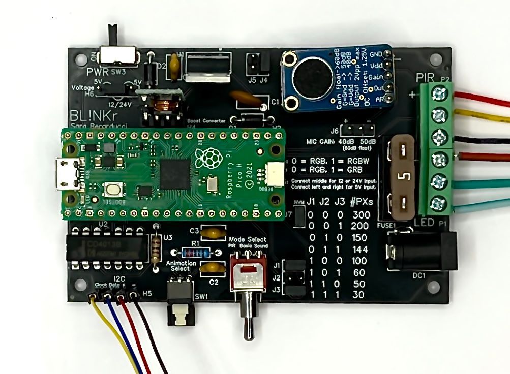
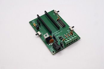
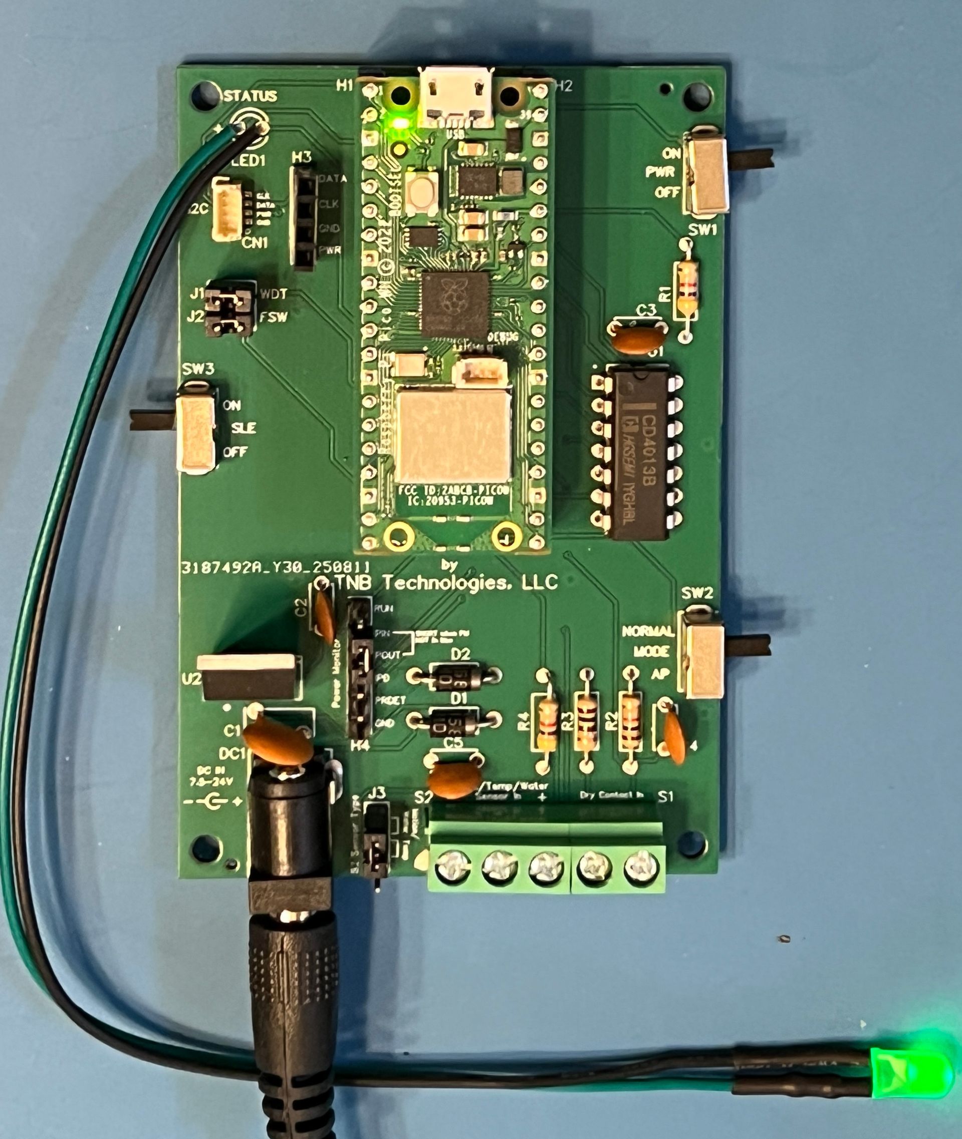
Seriously, get all the parts organized. See the picture below for all PC-Board parts. These are all the parts soldered onto the SensorNode PC board, and they are all included in the "bag of parts" reward. If you need more, refer to the parts list above.
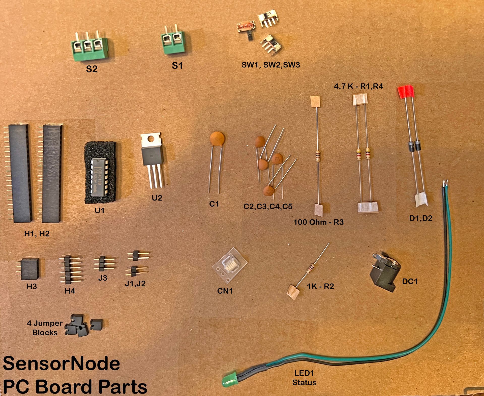
First, make sure you have them all and understand their designations. This is how you know where to place them on the circuit board. For example, in the parts list (above), R1 is a 4.7K ohm resistor. Look on the board and you'll see where R1 goes. If in doubt, look at one of the pictures above of a fully-assembled board to be sure. This is especially important for "polarized" parts. That is, parts that must be oriented a certain way. One example in the SensorNode design is the set of two diodes, D1 and D2. They MUST be oriented as shown in the pictures, or SensorNode will not work. So be careful.
After you have all your parts together, I suggest placing them on the board and bending the pins a little so they stay there. You can also use Blue-Tak or some equivalent. I use this to make sure parts don't fall out of the board before I've soldered them. Stick them down, then turn the board over and solder all the parts carefully. Sometimes it's easier to do the bigger parts first, then finish with the smaller parts. Up to you.
Once you've soldered all the parts, trim off the excess leads with some diagonal cutters to make things nice and clean. Now you are ready to add the pico, set the jumpers, power it up and go!
NOTES:
- Use ALL the parts. No really. There are not spares like with Ikea furniture :) Also I strongly suggest using headers H1 and H2 instead of trying to solder the Pico directly to the board. It's not that easy, you may damage it, and it's possible you may want (or have to) replace it sometime in the future.
- The ONLY exception to #1 above is part CN1 - This is a surface mount part which, while easy enough to solder with the right tools, can really suck if you don't know how to. Luckily, I've add header H3 which mirrors all the connections of CN1 so if you are hand-soldering your SensorNode, I suggest skipping CN1 and just using H3 for I2C. Besides, I designed H3 so that the ONLY part supported currently, the Adafruit AHT20, will plug directly into H3 with no problems. So you should be good to go.
Program Your Pico
The next step is to program your pico. This is really very easy to do. The Pico is designed to emulate a USB Memory Stick when plugged into a computer (mac, windows, or linux). So all you need to do is plug a compatible USB cable (micro USB on the Pico end) into the Pico, and then into your computer. It should show up as a drive labeled "RPI" when it is unprogrammed.
Two Ways to do this
You can program your Pico before you plug it into the SensorNode PC Board, or you can do it after, your choice. It's convenient to be able to program your Pico while still plugged into the SensorNode board because at times you may want to REPROGRAM the existing Pico setup, and it's a pain to unplug the Pico if you don't have to.
The ONLY THING you MUST REMEMBER when attempting to program your Pico while it is still plugged into the SensorNode Board is that FIRST YOU MUST DO THE FOLLOWING BEFORE PLUGGING THE CABLE INTO YOUR COMPUTER:
- TURN POWER OFF to your SensorNode using SW1.
- REMOVE Jumper J1 - this DISABLES the Watchdog Timer. Otherwise, the Pico may continuously restart while plugged into your computer.
- REMOVE Jumper J2 - this ENABLES the computer to write to the on-board storage of the Pico. Otherwise, you will not be able to add/update files on your Pico.
After this, programming your Pico is done exactly the same as if it was not plugged into the board at all.
To program your Pico, simply drag the appropriate files to this drive IN THE PROPER ORDER as detailed in the github repo documentation. In a minute or so, you should be done!
Programming Steps Summary - After you have attached a new Pico to your computer, perform the following steps:
- Drag or copy/paste "circuitpython" uf2 file to the unprogrammed Pico. After it copies, the Pico will disappear and reappear as "CIRCUITPY" on the desktop. If this does not happen, you have done something wrong.
- DELETE ALL FILES You see on the pico.
- Open the "code" folder. Drag all files from "code" folder to the Pico.
- Drag the entire "lib" folder to the Pico.
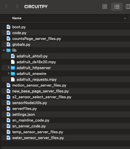
--> When you are done, the Pico's directory should look like this*:
* You may or may not see files named 'boot_out.txt' or 'settings.json'. Don't worry if you don't see them. They will be created for you when needed.
When you are done programming, simply 'eject' the Pico as any other USB Stick and unplug the cable. If the Pico is not yet plugged into the SensorNode board, plug the Pico into the board as shown in the various pictures, with the USB port facing UP towards the edge of the board. Make sure all the pins go into the headers properly.
Don't forget to REPLACE Jumpers J1 and J2 before starting your SensorNode!
Now you have a properly built SensorNode!
After this step, simply follow the Quick-Start Guide above, or take a look at the detailed Operating Instructions below.
Detailed Operating Instructions
If you really want to know the details about SensorNode, then read on.
Attaching Sensors
It's important that you always attach/remove sensors to SensorNode with the power OFF. Otherwise, you might short something that can damage your SensorNode.
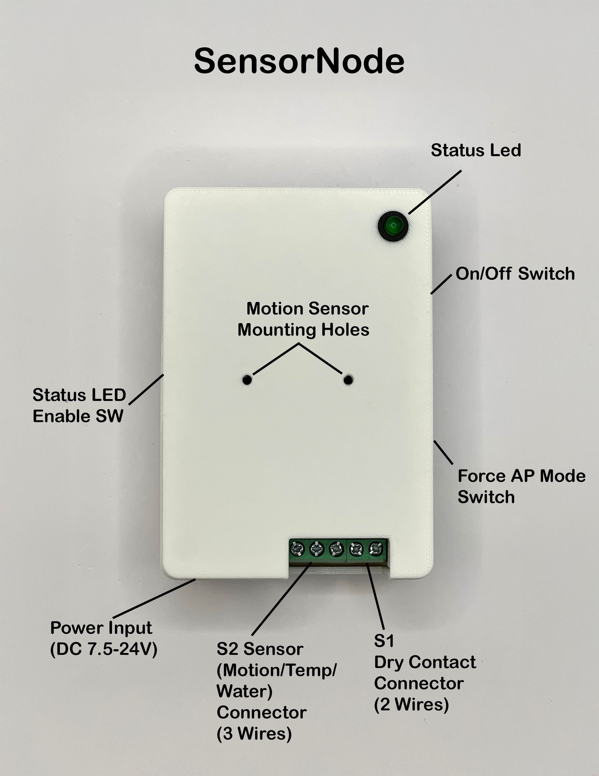
See pictures above for Sensor Connection areas.
See Parts List above for Sensors I have personally tested with SensorNode.
Currently, there are 4 types of Sensors that can be attached to SensorNode:
- S1 - Contact Closure Sensor - For this type of sensor you use Terminal Block S1, a 2-conductor terminal block. This is basically anything that shorts two contacts together, like a passive switch. You should NOT install any 'active' components (i.e. components that provide or require power of any kind) on connector S1. Since S1 is for passive components, it doesn't matter which way you install the wires. There is no polarity. For more info, look at this video I created.
- S2 - You can use terminal block S2 for THREE TYPES of sensors. Each Sensor has the same connections: Power (5V), GND, and DATA. They are labled on the circuit board with "+" for power and "-" for GND. Data is the CENTER connection. With ALL S2 Sensors, you MUST ALSO connect Jumper J3 properly depending upon which sensor you are using. See below for Jumper J3 setting details. The 3 possible Sensors for S2 are:
- Digital Temperature Sensor - This is intended for the popular Dallas Semi "DS18B20" type of digital temperature sensor. They are available at many places (Amazon, Adafruit, Alibaba, etc.). Just make sure you connect up the leads properly. Typically RED is Power, BLACK is GND, and the remaining one is DATA. But since this sensor is made by many companies, no guarantees. Check the sensor's documentation before connecting.
- Motion Sensor (PIR or HPD) - You can use EITHER a PIR (Passive Infrared) OR a HPD (Human Presence Detect) sensor in this case. For PIR I recommend the Adafruit version because I've tested it. WARNING: You MUST make sure you connect Power and Ground PROPERLY otherwise you may damage your sensor, the SensorNode PC board, or both. PLEASE SEE THE VIDEO. BE CAREFUL because many of these sensors have MIRROR-IMAGE connections! Consult the sensor documentation carefully prior to connecting. Also the ONLY HPD I have tested with is the LD2410C version. Consult the parts list above for the exact variant. Again, make sure you connect the leads properly before powering up. For more info, check out this video I made about connecting a PIR Motion Sensor to your SensorNode.
- Water Sensor - This is designed to accommodate the ADAFRUIT water sensor (consult parts list above) only. Again, 3 wires - Power, GND, and data.
- CN1 OR H3 - I2C Temp/Humid Sensor - This is an I2C sensor connection, but to date I have only enabled use of ONE type of I2C sensor - the AHT20 combo temperature/humidity sensor. Again I recommend using the ADAFRUIT version, but many variations exist (at lower prices). But also again - you MUST make sure the connections are correct, otherwise you may break your SensorNode, the AHT20 board, or both. Different products may use different color codings so don't rely on that - always check the manufacturer's documentation! Also, I2C is an "open drain" connection and as such requires pull-up resistors. The Pico can be programmed to provide pull-ups, but they may not be adequate for all I2C connections. Luckily, the Adafruit AHT20 board provides external pull-up resistors. If you are using anything else, beware of this. For more info on setting up this sensor, see the video I've made about it.
Setting Jumpers
It's important that you set the jumpers for SensorNode properly before powering up the device. There are FOUR possible Jumpers to set up:
- J1 - Watchdog Timer Enable - Setting this jumper (i.e. shorting the two pins associated with it by using a Jumper Block) will ENABLE the SensorNode Watchdog Timer (WDT). This will reset the SensorNode if for some reason it freezes up (FYI I have NEVER seen this happen). This is an excellent safety feature and helps ensure SensorNode keeps running 24/7/365. NOTE: If you ever want to connect SensorNode to a computer (to reprogram it or change the code) you should REMOVE this jumper. Otherwise SensorNode will continually RESTART and you won't be able to connect to it reliably with your computer. NOTE: If the Watchdog Timer is disabled, the 'Normal' LED light flashes will be cut to one quarter the frequency. That is, normally the LED will flash approx 2Hz when SensorNode is operating. If the Watchdog timer is disabled, it will flash much slower, approx 0.5Hz. Access Point operation is NOT affected by WDT settings.
- J2 - File System Write Enable - Setting this jumper will ENABLE the SensorNode to write to its own internal flash memory. This is necessary for SensorNode to alter its settings. But, as with J1 above, if you ever want to attach SensorNode to a computer to modify its memory, you MUST REMOVE this jumper otherwise the computer will not be able to write to SensorNode's memory.
- J3 - S2 Sensor Type - This jumper MUST be in the proper orientation if you use a sensor connected to Terminal Block S2. You should short the BOTTOM TWO pins if you are using a digital temperature sensor, and you should short the TOP TWO pins if you are using either a motion sensor OR a water sensor. If this jumper is not set correctly, erratic or erroneous behavior may result.
- H4 - REQUIRED - Power Pass-Through - The H4 Header is a 6-pin header originally designed to accomodate an optional Power Monitor daughtercard. This daughtercard did not make it into the original SensorNode Kickstarter project. In order for SensorNode to operate properly without a Power Monitor installed, you MUST short pins 2 and 3 (refer to pictures above) labeled PIN AND POUT.
Switches
There are THREE Swtiches on SensorNode. They are used for the following functions:
- SW1 - Power - Pretty self-explanatory. When UP in the ON position, power is provided to all SensorNode components. NOTE however that some components use 3.3V and some get 5V. Note also that, even if this switch is in the DOWN/OFF position, there is still POWER in some areas of the board! Best way to ensure there is NO power anywhere is to unplug the board from the power supply.
- SW2 - Mode - This switch,when DOWN in the AP position, will force the SensorNode to go into Access Point Mode following a restart. Normal operating mode is UP. NOTE if SensorNode cannot get on the WiFI or cannot attach to Home Assistant, it will automatically go into AP mode regardless of this switch setting. And, after a short delay OR 'Submit and Restart' is clicked on the Configuration Home Page, SensorNode will automatically attempt to restart into Normal mode. To force SensorNode into AP mode, flip this switch to the DOWN/AP position, turn off power using SW1, wait a couple seconds, and then turn power back on. NOTE as long as SW2 is in the AP position, SensorNode will NEVER go into Normal operating mode! So remember - after you are done editing/adding/changing settings, flip SW2 to the 'Normal" position, and THEN click "Submit and Restart" to restart into Normal mode!
- SW3 - Status LED Enable (SLE) - This switch will allow you to turn OFF all LED lights regardless of software settings. This is useful if SensorNode is placed in an area you don't want it to be noticed, or if you don't want to disturb people with flashing lights. You can always turn the lights back on (as long as they are enabled in the settings) by flipping the switch to the ON position.
Startup
When any SensorNode starts after power is turned on, it will attempt to join the local WiFi network. If for some reason it cannot join the network (it doesn't have credentials stored, the network is down, SensorNode is placed in an area of weak signal, etc.) it will fail the connection attempt. SensorNode will then retry the connection attempt FIVE times. If, after 5 retries, it still cannot get on the network, SensorNode will restart into Access Point (AP) Mode. You will know this is the case because the Status LED will be flashing FAST (approx 4Hz) while SensorNode is in AP mode. It is at this time that you can use a computer or smartphone to attach the the SensorNode AP. You do this by going to your wireless settings in your device, and looking for an AP named "SensorNode-XXXXXXXXXXX", where the long string of X's represent the SensorNodes Unique ID. Once you attach to the AP, you can open up a browser on your device, and enter the SensorNode AP IPAddress into the browser search bar/IP Add area. The default SensorNode AP IPAddress is "http://192.164.4.1". At this point, the SensorNode Configuration web page will open up, and you can enter/modify settings.
Startup Notes
Access Point Operation
When a SensorNode goes into AP mode, you have 60 seconds to attach to the AP. If you do not attach within 60 seconds, SensorNode will restart into normal operation mode (i.e. 'station' mode). At this point, SensorNode will repeat the process detailed above and try to get on the network. This is useful in cases when SensorNode has valid credentials, yet falls off the network for other reasons (network goes down temporarily, weak WiFi signal, etc.). There ARE EXCEPTIONS to this behavior, however. If SensorNode does not have any credentials stored, it will NOT attempt to restart (cause that would be stupid). Also, if the MODE Switch (SW2 on the board) is in "AP" mode (down), SensorNode will NOT attempt to restart. That way, you can keep SensorNode in AP mode as long as you want. Then, when you are done, simply switch this switch UP into "Normal" mode prior to hitting "Submit and Restart" (or prior to cycling power) and SensorNode will restart into Normal mode. For more info on using SensorNodes built-in AP, click here.
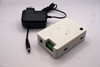
Powering Your SensorNode
If you do not have have access to, or for some reason cannot make use of, the 'official' SensorNode Power Supply, there are other ways to power your SensorNode. This section will discuss ways to do that.
Using the Barrel Jack Connection
SensorNode is designed to work with 5V power, but it has an on-board 5V regulator that provides this voltage when a larger DC voltage is supplied via the barrel jack connector (DC1). The SensorNode circuit board will work with any power supply that fits the spec for this connection, so you can probably easily obtain one regardless of where you are. Here are the specs:
- Voltage to the board at the barrel connector: between 7-24VDC
- Current used by the board: less than 400mA
- Barrel Connector physical requirements: Center Positive, 5.5mm Outer Dimension (OD), 2.5mm Inner Dimension (ID)
Powering Over USB
Another way to power the SensorNode is by plugging a micro-USB cable directly into the Raspberry Pico W USB connector. You can then plug the other end into any compatible wall wort and then into your AC power mains. This should work anywhere in the world because USB is universally delivered as 5V to the Pico. The only issue with this method is you will not be able to turn the power off with the switch (SW1). You'll have to unplug the unit to cut power (or use a switched outlet).
DO NOT plug the SensorNode into a computer unless you know what you are doing and want to reprogram it. In this case, you'll need to disable the Watchdog Timer and Enable File System Write capability before you can access the Pico from the computer (i.e. REMOVE Jumpers J1 & J2).
Configuration using SensorNode's built-in Access Point
SensorNode is a 'one-way' device. That is, there is no way to talk to SensorNode from Home Assistant. That is actually one of its strengths. You see, other devices require 'integrations' with Home Assistant. Integrations are basically software interfaces between Home Assistant and the device. But SensorNode does not require an integration, because it makes use of the BUILT-IN HTTP Interface of Home Assistant. So there are no integrations to write, maintain, and update. Ever. Thus, SensorNode is much more likely to work, day after day, update after Home Assistant update, forever.
But, because of this, the only way to 'talk' to SensorNode is through its built-in WiFi Access Point (AP). This is necessary to configure SensorNode for first use, and subsequently whenever you want to change these settings. Luckily, this is very easy to do.
To access SensorNode's AP, do the following:
- Turn off the power (SW1).
- Flip SW2 into AP mode.
- Turn back on the power (SW1).
Now, when SensorNode turns back on, it will be 'forced' into AP mode (because of SW2). You will know this is so because the LED will be flashing twice as fast as normal, approximately 4Hz. At this point, you can now access the AP using your computer or smart phone.
To do this, do the following:
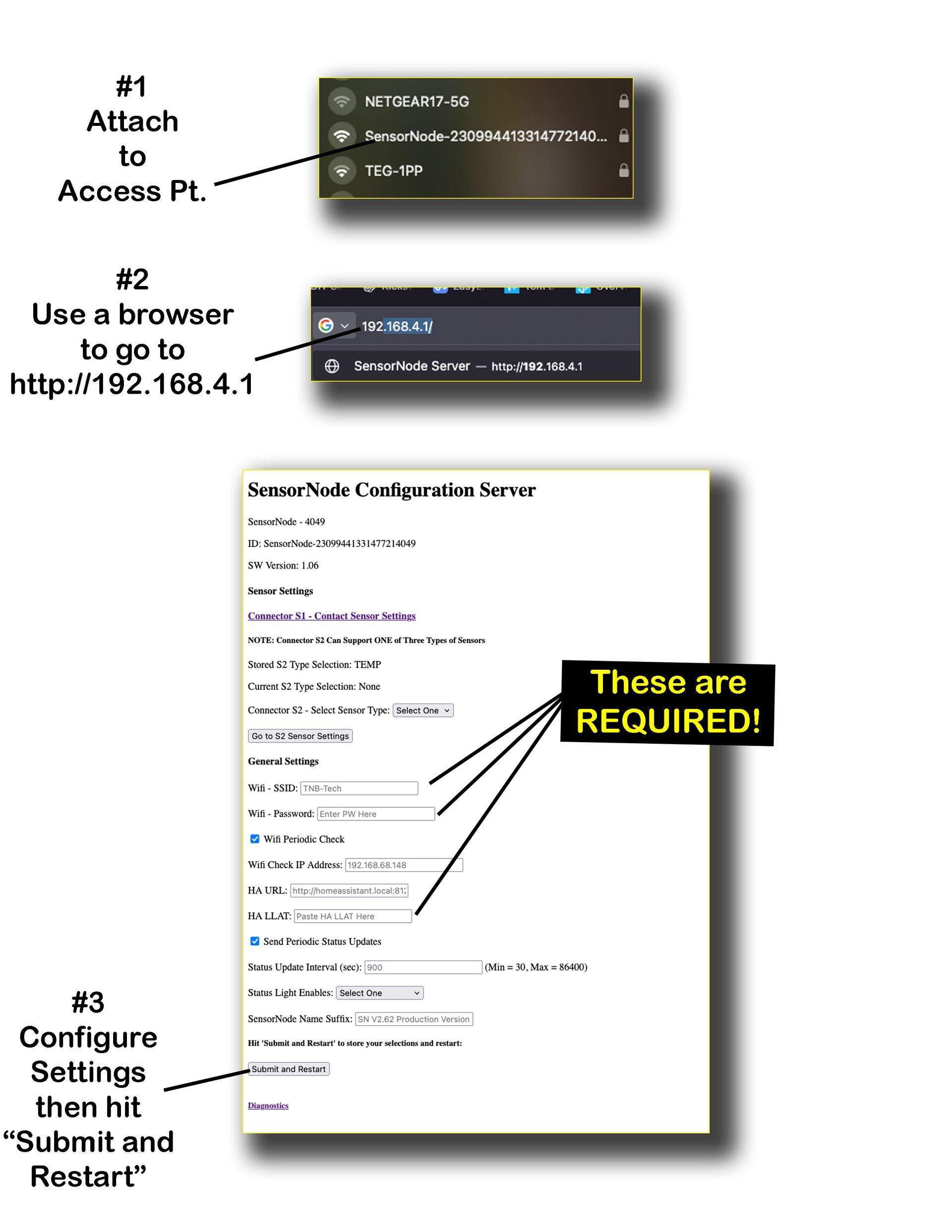
- On your computer or smart phone, first go to your WiFi settings and look for an Access Point with the name: "SensorNode XXXX..XXXX" where the X's represent the unique ID of the SensorNode. This way, multiple SensorNodes could be broadcasting at once and you can still pick out the one you want. Select the one you are interested in, and connect to it just like any other WiFi Access Point.
- Once connected, open a browser window and type in the SensorNode's Configuration Web Page IP Address. The default is "http://192.168.4.1".
You can change this in the globals.py file if you want. After you do this the Configuration Web Page should open.
Detailed Description of SensorNode Configuration Server Settings
- SensorNode XXXX - At the top of the page, you'll see this designation which shows the last 4 digits of the SensorNode unique ID. This 4-digit number appears many places to help you identify which SensorNode you are dealing with in Home Assistant.
- ID - This line shows the complete unique ID of the SensorNode. It will also appear in the attributes section of the SensorNode binary sensor entry in Home Assistant.
- Sensor Settings - This section has two parts, one for connector S1 and one for connector S2 on SensorNode.
- S1 is used for Contact Closure Sensors. To adjust the settings, click on "Connector S1 - Contact Sensor Settings". You will be taken to the S1 Sensor Settings Page where you can enable the sensor, give it a unique name, and adjust it's Active Duration.
- S2 is used for one of THREE types of sensors: Temperature, Motion, or Water. To set up this sensor, you must FIRST Select the Sensor Type you want to configure by clicking the "Select One" drop-down box and selecting the sensor type you want to configure. Only ONE sensor type can be configured for this connector at any time. You can always change this later if you wish. After you have chosen the sensor type, then click on "Go to S2 Sensor Settings" and you will be taken to that specific sensor type's Settings Page, where you can enable the sensor, give it meaningful name, and adjust any other parameters relating to it.
- NOTES about Sensors:
- For S1 and S2 sensors you MUST at minimum ENABLE the sensors in the sensor settings. This tells SensorNode that you want sensor values sent to Home Assistant. Otherwise no values will be sent!
- Regardless of what name you give to your sensors, the text "- XXXX' (last 4 digits of the unique id) will ALWAYS be appended to the end of that name, so that you can always tell which SensorNode you are looking at, and which sensor is associated with it.
- For S2 Sensors, you MUST also make sure Jumper J3 is set properly on the SensorNode circuit board.
- General Settings - Even if there are no sensors attached to SensorNode, the device will still appear in Home Assistant as a "SensorNode" binary sensor. This is useful to know that the SensorNode is functioning normally, as well as allowing you to read the attributes and enable useful automations. Several General Settings are necessary for proper operation of SensorNode:
- Wifi SSID and Password - REQUIRED - You must enter the credentials for your local WiFi. This must be the same network your Home Assistant install is located on.
- WiFi Periodic Check - If checked, SensorNode will check the WiFi connection every 5 minutes to make sure it is still connected to the WiFi. You also must enter an IP Address to check in the box provided. I suggest using the address of your Home Assistant install if it is static. You MUST ensure this IP Address is static otherwise SensorNode will get stuck checking addresses that don't exist!
- NOTE if you do not enter an IP address, the check will not take place even if you check the box. If the check fails, SensorNode will retry 5 times. If after that it still fails, SensorNode will restart.
- HA URL - This is the URL used to access Home Assistant. It should be the same URL you use to access the Home Assistant web page. The default URL (http://homeassistant.local:8123) is entered by default. If you are using this URL you should not have to touch this setting. If you are not, you MUST enter the proper URL or SensorNode will fail to connect to Home Assistant.
- HA LLAT - REQUIRED - This is where you must enter your unique Home Assistant "Long-Lived Access Token" in order to allow SensorNode to access Home Assistant. You obtain this token from Home Assistant, under the 'user' area of your install. Follow these steps to generate your LLAT:
- On your Home Assistant Main Screen, scroll the left-hand menu to the bottom and select your User Name.
- In the main window area you should then see two tabs: "General" and "Security". Select the tab labeled Security.
- Scroll to the bottom where it says "Long Lived Access Tokens".
- Click on "Create Token".
- In the dialog box that appears, give your token a name and click OK.
- IMPORTANT - The next thing that will appear is a dialog box with your Long-Lived Access Token (LLAT) visible. You should copy this token at this time, because it will NOT be visible any longer for security purposes. Copy it into a text file, labeled so you can find it later, and store it in a secure place. You can use the same LLAT as many times as you want.
- PASTE this LLAT into the "HA LLAT" area of your SensorNode settings screen.
- Close the Home Assistant dialog box by clicking the "X". You will see the token on your Home Assistant screen, but you will no longer be able to read it's contents. If you mess this up, don't worry! You can simply delete this token from Home Assistant and repeat this procedure as many times as you need.
- Send Periodic Updates/Update Interval - If checked, SensorNode will send an 'online' signal to Home Assistant periodically to tell Home Assistant that it is still online. You can use this to set up an automation to alert you if your SensorNode ever goes offline. The default update interval is 900 sec (15 min) which I find is a good tradeoff between timely notifications and network chatter. You can change this if you like.
- Status Light enables - Select this drop-down box and choose one of the following:
- Internal - ONLY the LED on the Pico will flash.
- External - ONLY the GREEN LED at the end of the long cable will flash.
- Both - BOTH LEDs will flash.
NOTE that, while switch SW3 will control if the status lights are ON or OFF, this setting allows you to control WHICH lights will be illuminated if SW3 is ON.
- SensorNode Name Suffix - You can use this field to optionally add a descriptive name your SensorNode Binary Sensor that appears in Home Assistant. By default, this name will be "SensorNode - XXXX", where XXXX is the last 4 digits of the SensorNode's unique ID. If you add text to this setting, that text will be APPENDED to the end of this default name. For example, if I added "Test" to this setting, then my SensorNode Binary Sensor in HA will have the name "SensorNode - XXXX - Test".
- Submit and Restart - NOTE first MAKE SURE the MODE SWITCH (SW2) is in the DOWN/Normal position before restarting (otherwise SensorNode will keep restarting into AP mode)! Click this button when you are done editing settings and SensorNode will restart.
For more detail on how to configure settings, watch the "Setting Up Your New SensorNode video.
Interaction with Home Assistant
When SensorNode connects with Home Assistant, data will show up as various sensors, either binary sensors or analog sensors, depending upon type. These are the types of sensors that will show up on your default Home Assistant 'Overview' dashboard:
- SensorNode Binary Sensor - This will ALWAYS show up if SensorNode is operating properly. By default, it will show up as "SensorNode - XXXX" where the X's represent the last 4 digits of the SensorNode unique ID. If you add a custom name to SensorNode in the settings, this name will be APPENDED to the end of this text.
- Contact Sensor Binary Sensor - IF ENABLED IN SETTINGS - This is the sensor attached to connector S1. By default, it will show up as "Contact Sensor - XXXX" where the X's represent the last 4 digits of the SensorNode unique ID. If you add a custom name to this sensor in the settings, the 4-digit ID will be APPENDED to the end of this text.
- S2 Motion Binary Sensor - IF ENABLED IN SETTINGS - if you SELECT 'Motion' as your S2 sensor type and enable this sensor, it will show up by default as "Motion Sensor - XXXX" where the X's represent the last 4 digits of the SensorNode unique ID. If you add a custom name to this sensor in the settings, the 4-digit ID will be APPENDED to the end of this text.
- S2 Temperature Analog Sensor - IF ENABLED IN SETTINGS - if you SELECT 'Temp' as your S2 sensor type and enable this sensor, it will show up by default as "Temperature Sensor - XXXX" where the X's represent the last 4 digits of the SensorNode unique ID. If you add a custom name to this sensor in the settings, the 4-digit ID will be APPENDED to the end of this text.
- S2 Water Binary Sensor - IF ENABLED IN SETTINGS - if you SELECT 'Water' as your S2 sensor type and enable this sensor, it will show up by default as "Water Sensor - XXXX" where the X's represent the last 4 digits of the SensorNode unique ID. If you add a custom name to this sensor in the settings, the 4-digit ID will be APPENDED to the end of this text.
- I2C Temperature Analog Sensor - IF I2C Add-on Board is installed - it will show up by default as "I2C Temperature - XXXX" where the X's represent the last 4 digits of the SensorNode unique ID. You can NOT add a custom name to this sensor.
- I2C Humidity Analog Sensor -
IF I2C Add-on Board is installed - it will show up by default as "I2C Humidity - XXXX" where the X's represent the last 4 digits of the SensorNode unique ID. You can NOT add a custom name to this sensor.
Using SensorNode Sensors in Home Assistant
You can use any of these sensors with Home Assistant just like any other sensor of its type. When using one of these sensors, it is helpful to simply start typing the 4-digit ID, and Home Assistant will bring up the matching sensor.
You can add SensorNode sensors to custom dashboards, in automations, etc. When searching for a sensor (like in the 'Overview' dashboard) simply type the 4 digit ID, and the sensor should show up. If you are unsure of the ID, simply type "SensorNode" and all the SensorNode binary sensors will show up.
Useful Home Assistant Automations
Online/Offline Automation - I find it very useful to get notified if a SensorNode has fallen off the network and/or detached from Home Assistant. The occurrence of this is extremely rare, as long as the watchdog timer is enabled on your SensorNode. But it can occur, for instance if the SensorNode is placed in an area of low WiFi signal, or if SensorNode gets unplugged by accident, or damaged somehow. In cases such as these, you will want to be notified that your SensorNode is offline. This is how to do that easily using Home Assistant:
- Create a Helper called "SensorNode XXXX Online" - use a 'toggle' helper.
- Create an "online/offline" automation for your SensorNode. You will need two triggers:
- "Online" trigger - use this line for the trigger: entity "SensorNode - XXXX" changes from any state to any state. This basically will fire if the SensorNode binary sensor sends any info to Home Assistant.
- When this trigger fires, set its action to toggle the "SensorNode XXXX Online" helper ON.
- "Offline" trigger - use this line for the trigger: {{ now() - states.binary_sensor.sensornode_xxxx.last_changed > timedelta(minutes=35)}} - and replace the "xxxx" with the 4-digit ID for this SensorNode.
- When this trigger fires, set the action to toggle the helper OFF, and to optionally send a notification telling you this SensorNode is OFFLINE.
NOTES:
- This automation will only work if you have "Send Periodic Updates" properly configured and enabled in the settings. If enabled, SensorNode will send a signal to Home Assistant periodically, which will act to trigger the automation, keeping the helper set to TRUE/ON.
- By putting this into an automation, your helper will be TRUE/ON when your target SensorNode is ONLINE, and it will be FALSE/OFF when your target SensorNode is OFFLINE. If you want, you can set the automation to send you an ALERT whenever your SensorNode goes offline.
- By default, the Send Periodic Updates setting is set to 900 seconds, or 15 minutes between updates. That is why the "minutes=35" is set, giving SensorNode slightly over TWO UPDATE INTERVALS to report in. After that, it will be marked as OFFLINE. If you change the update interval, you should also change the 'minutes=' value as well to accommodate this change.
Modifying the "globals.py" File
You should never have to change any of the SensorNode code. But if you want to, most of the more useful global settings for SensorNode can be found in the "globals.py" file of the SensorNode code. This section details what these settings do.
FAQ / Troubleshooting
If you are having problems with your SensorNode (gasp!) - then the info below should help you out.
How do I change Settings??
Remember you can always change/add/edit your SensorNode's settings by forcing it into Access Point (AP) mode. You do this by turning off power, flipping the MODE switch (SW2) to AP, and turning the power back on. For more details, see the section on using the AP to configure your SensorNode.
I turned on my SensorNode for the FIRST time, but nothing happens!
For a new, clean install SensorNode, the unit should start up in Access Point Mode because it won't be able to get on your Wifi without credentials. When this happens, you should see the LED flashing rapidly (approx 4 Hz or 4 times per second).
If this does NOT happen, then these are the possible reasons:
1. (Most likely) - The status led enable Switch (SW3) might be in the OFF position (see diagrams above). If so, SensorNode will be in AP mode but you will NOT see any flashing lights. To remedy this, simply flick the switch to the ON position.
2. (Unlikely but possible) - Some Picos have an extra-long serial number. This serial number is used for the basis of the SensorNode Unique ID and ALSO for the basis of the AP SSID. If the number is too long, however, earlier versions of the SensorNode code will break. If this happens, SensorNode will continuously restart but if may happen so fast that you might not see any LED action regardless of the position of SW3.
To fix this - download the latest version of the SensorNode code from the github repo and reprogram your SensorNode by following the instructions above.
I restarted my SensorNode after modifying settings, but nothing happens!
Possible issue #1 - If you do not enter proper credentials for your Wifi, then SensorNode will not be able to connect to WiFi when it starts. If this happens, SensorNode will automatically go into Access Point (AP) mode. You can tell this is happening if the LED is flashing FAST (approx 4Hz) - make sure the LED enable switch (SW3) is ON or you will see nothing. If this is the case, follow the instructions on how to configure your SensorNode using the AP.
Possible issue #2 - If you have entered valid WiFi credentials into your SensorNode settings, it's still possible that SensorNode will not work IF your Home Assistant install is NOT on the SAME WiFi network as the one you gave SensorNode credentials for. This can happen, for instance, if you accidentally put credentials for a Guest Network into your SensorNode, but your Home Assistant is on your Main Network or some other isolated network. If this happens, SensorNode will continuously REBOOT - the LED will be ON for along time, it will turn OFF for a few seconds, and then back ON, continuously, forever!
Possible issue #3 - If you enabled "Periodic WiFi Checks" in the settings, you MUST ensure the IP Address you enter there is STATIC or RESERVED. That is, it CANNOT CHANGE. Some networks dynamically allocate IP Addresses for clients, so that each time they restart, their assigned IP Address may be different. If this happens, SensorNode will not be able to reach this test address and it will appear to be dead, continuously rebooting as indicated above. If you don't know how to make sure IP addresses on your network do not change, I suggest you do NOT enable this feature.
BOTTOM LINE --> Make SURE you have put proper credentials for your WiFi in your SensorNode settings and make SURE SensorNode is on the same WiFi network as your Home Assistant install!
I'm SURE I entered the proper WiFi credentials but still nothing is happening - HELP!
I strongly suggest you MAKE sure you have checked all the issues above before you take this step.
Every time SensorNode starts up, the LED on the Pico will blink 4 times rapidly. That tells you SensorNode is starting to execute its code. If this does not happen, that means for some reason, it cannot. This is typically because the code is not there. On RARE occasions, due to mishandling, power glitches, static electricity, phases of the moon, barometric pressure, blah, blah, blah, the SensorNode code can simply "disappear". I've seen this once or twice over a 3 year period with dozens of Picos, so it is unlikely but not impossible. If this happens, you can check by carefully removing your Pico from the board and plugging your Pico into a computer using its micro-USB port. If the Pico is working properly, it should appear as a disk drive. Check to see if all the software is still there, and if not, reprogram your Pico as indicated in the instructions above.
(Honestly, this is highly unlikely to be the case, but since I've seen it happen myself I thought for completeness I'd add it here.)
OK this time I'm REALLY sure I have the proper credentials, but the LED is flashing rapidly and the SensorNode is still not working!
I hooked up my Temperature Sensor, enabled it in settings, but it is not showing up in Home Assistant
If this occurs, mostly likely you have not set Jumper J3 properly. Check it and make sure it is set to indicate "TEMP" by shorting the bottom two pins!
I followed the Quick-Start and added my sensors like it said in Step #1. But no sensors are showing up in Home Assistant. My SensorNode is there, but the attributes say "No Sensors Found"
To get sensor readings from SensorNode into Home Assistant, you must not only physically attach these sensors, but you must also ENABLE them in the SensorNode Settings. This applies to any sensor attached to connector S1 or S2. The I2C Temp/Humid combo sensor will get detected automatically.
I hooked up a motion sensor, but now my SensorNode appears DEAD!
If you do not connect power and ground properly, your SensorNode may not work and may actually appear to be dead.
Just disconnect power, and check your connections. After connecting it properly, it should work.
Remember - for all S2 Connector Sensors, you must:
- Connect sensor leads correctly.
- Place Jumper J3 correctly.
- ENABLE the sensor in the settings.
Resources
Here are some useful resources for understanding and using your SensorNode. The videos below go into extreme detail about setting up and using your SensorNode. Enjoy!